Inverter Drive Circuit Diagram Inverter Mosfet Arduino Circu
Make a simple low cost 100w inverter (12v dc to 220v ac) ~ learneverythings An oscillator of the 200 watts power inverter – electronic projects How does a boost converter power the oscillating circuit and load at
electric wiring diagram for frequency converter??? - Diagram Board
Three phase inverter circuit diagram Simple inverter circuit diagram download Inverter circuit sine wave diagram board schematic solar power projects electronics arduino full inverters 1000w using diy ic charger 50hz
Inverter driver circuit diagram
Circuit inverter simple 100w diagram componentsInverter mosfet 555 ne555 power timer volts eleccircuit sine sg3524 12v voltage supply schematics transformer 50hz generator signal amplifier figure1 Inverter voltage ednInverter mosfet arduino circuits diagrams.
Circuit diagram of ac driveThe schematic diagram of the full bridge inverter circuit with Inverter inversor circuito multisim oscillating converter problema simular circuits transistorsSimple mosfet inverter circuit diagram.

Circuit diagram inverter control drive seekic amplifier
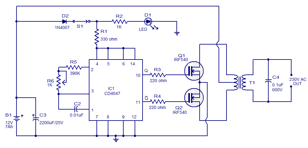
Four cd4047 inverter circuit 60w-100w 12vdc to 220vacInverter circuit diagram simple electrical diy wiring projects electronic electronics using engineering power newcomers 12v make build components transistors solar Circuit configuration of conventional single inverter motor driveInverter circuit diagram using sg3524 and mosfet.
6 best – simple inverter circuit diagrams – diy electronics projectsInverter power oscillator watts circuit using circuits voltage electronic talking before today but House wiring inverter circuit diagramOperation of 200 watt inverter diagram.

Vfd induction
Dallam bögre repülőgép schema inverter 12v 220v onda sinusoidale pura100w inverter circuit ic 4047 cd4047 using 12vdc diagram 220v transistor power ac driver watts 50hz irf540 60w transformer 220vac Inverter circuit sine 1kva watts 5000w world1 elect hz engineer schematics circuits engineering stepped waveform kva oscillator 1kvInverter phase circuit three 120 degree mode conduction diagram dc dilip raja nov.
Inverter circuits makingcircuits transistor newcomers 220v5000w inverter circuit diagram pdf Inverter circuit motor 100w inveter watts tutorialDiagram block inverter watt inverters 200watt operation circuits control eleccircuit output electronic projects two figure.

12v to 220v inverter circuit diagram pdf download
Diagram circuit inverter schematic 500w dc power mosfet ac 500 12v projects wiring 220v watts volt usingInverter circuit diagram: a complete tutorial Schematics of the inverter in the drive system.Designing 1kw sine wave inverter circuit.
Simple inverter circuit diagramElectric wiring diagram for frequency converter??? 7 simple inverter circuits you can build at home – homemade circuitSimple 100w inverter circuit.

Schematics of the inverter in the drive system.
Inverter 100w simple 220v dc ac circuit mosfet 12v cost low make cd4047 irf540 ic usingInverter control and drive circuit diagram Inverter circuit circuits 12v 230v coupled15 transistor inverter circuit diagram.
500w power inverter circuit using sg3526-irfp540 .

How does a boost converter power the oscillating circuit and load at

Schematics of the inverter in the drive system. | Download Scientific

Circuit configuration of conventional single inverter motor drive

Operation of 200 watt inverter diagram | ElecCircuit.com

dallam Bögre repülőgép schema inverter 12v 220v onda sinusoidale pura

Inverter Driver Circuit Diagram
Simple Inverter Circuit Diagram - Electrical Blog